LC Baluns
Sometimes, when working with RF, there will come a situation where one device being used has a balanced input or output but the device which it needs to electrically connect to has a singled-ended or unbalanced input or output. Often these devices will also have different impedances. In these situations, you need to construct a balun (balanced to unbalanced) circuit to bridge these two types of RF terminals together.
Balanced RF ports usually are designed to drive or be driven by something like a dipole antenna. Unbalanced RF ports usually are designed to drive or be driven by something like a typical 50 ohm coax cable or a monopole antenna. Attempting to directly connect a balanced RF port to an unbalanced one, even if the impedances match, will result in poor RF performance.
Usually baluns are made with transformers. Most every amateur radio design book will show how to construct a magnetic core balun for use at various frequencies and power levels. But in low cost consumer or similar circuit board designs, a transformer based balun may be too expensive or too large, or simply impractical for other reasons.
When a transformer based balun is not reasonable for the design, one option is to create an LC balun, using only capacitors and inductors.
The goal is to take each of the balanced port pins and introduce a 90 degree phase shift (one +90, one -90) while matching the impedance to, for example, 50 ohms, such that the unbalanced device has a proper reference.
You can see an example of a 868/915 MHz LC balun in the datasheet for TI’s CC1101 radio in figure 11 on page 25:
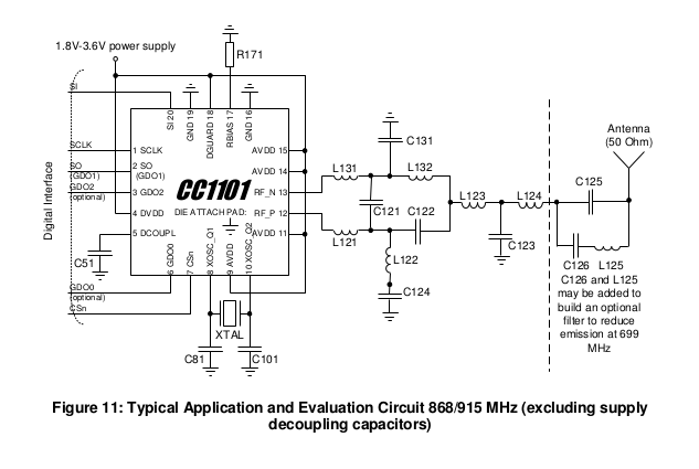
A few different things are happening in the circuit between the antenna and pins 12 and 13 (RF_P and RF_N), but since the output antenna is single ended (usually an SMA connector for coax cable or a monopole PCB antenna in most CC1101 designs), a balun is needed. Since the CC1101 RF port has an impedance of 86.5
- j43 ohms at 868/915 MHz, as shown in section 4.3 on page 16, the impedance also needs to be matched to 50 ohms to match the antenna.
So what the heck is going on here?
Let’s assume we want to tune this circuit for 900 MHz, that should get us close to the ideal for covering both the 868 and 915 MHz bands. With this assumption, that +j43 ohms reactance of the CC1101 needs to be canceled out. To do this, L131 and L121 add to the inductance of the CC1101 such that a standard 1 pF capacitor can cancel our all of the reactance. A 1 pF cap at 900 MHz is roughly -j176 ohms, while the pair of inductors (L131 and L121) add to about +j135 ohms. Adding the CC1101 reactance of +j43 ohms to the +j135 ohms and subtracting the C121’s -j176 ohms nets out to about a real impedance with no reactance (it’s slightly off at 900 MHz but that’s forgivable as the bands we’re working with are quite spread from each other so this is expected). Now, looking across the nets which span C121 into the CC1101 should look like just the real component of the CC1101 impedance of 86.5 ohms.
At this point, now we can try to match the 86.5 ohms impedance to 50 ohms (although this isn’t what TI appears to do with their given recommended values for this circuit). In order to bring the net on the left side of L123 to 50 ohms, which is the simplest balun (but which may have other downsides), we first have to calculate Rinner. Rinner will be used to calculate the L and C values which will apply to C131, C122, L132, and L122. These 4 components each will introduce a +90 and -90 degree phase shift and match the impedances, such that we end up with a real 50 ohm singled ended (unbalanced) point on the left side of L123.
Rinner = sqrt(Zunbal * Zbal)
Actual calculations:
octave:8> Rinner = sqrt(86.5 * 50)
Rinner =  65.765
Now to calculate the L and C values using our w (which is 2 * pi * f):
octave:9> w = 2 * pi * 900E6
w =  5.6549e+09
octave:10> L = Rinner / w
L =  1.1630e-08
octave:11> C = 1 / (Rinner * w)
C =  2.6890e-12
Thus, setting C131 and C122 as 2.7 pF and setting L132 and L122 as 11 nH should get us from the CC1101 to a single ended (unbalanced) 50 ohm match with the proper phase shifts.
We can try this out using the RFdude matching software to see the impedance transform when looking into the 50 ohm side of the circuit:
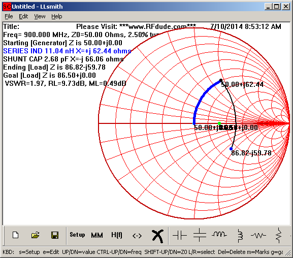
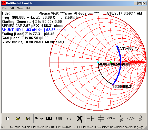
As each of the resulting impedances’ reactances roughly cancel each other out, we have successfully transformed from the single ended 50 ohm impedance to the balanced 86.5 ohm impedance.
I really don’t understand TI’s recommended values given in the CC1101 datasheet for 868/915 Mhz operation. Their match does not work for me. However, the given topology and values for their 433 MHz match works out fairly close when I use RFdude to evaluate it, however why they don’t cancel the reactance of the CC1101 in the 315/433 MHz topology is a mystery to me, since they do cancel it in the 868/915 MHz topology.
Atmel actually have a nice application note on this and their values actually do work out, which is nice.